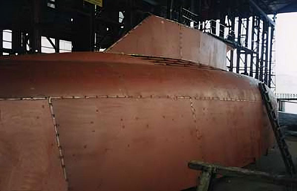
Radius Chine Hulls Explained
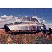
It is possible to build a round bilge steel or aluminium hull without the great time and effort, not to mention specialised experience, required using traditional steel outbuilding methods. There are several reasons for building a radius chine hull. Your boat will enjoy all of the benefits of a round bilge hull including superior appearance, strength, lighter weight and much higher resale value; all of this while maintaining the advantages of steel or aluminum construction.
These new radius chine building techniques are only possible with computer assisted, yacht design and computer fairing which provides the builder with full size patterns of all the frames and the stem. Also included are full size expanded and developed transom patterns. The secret of radius chine depends on fairing the radius through to the bow. Many previous attempts at this type of hull form have tried to fade out the radius before it reaches the bow. This usually results in an unfair area up forward.
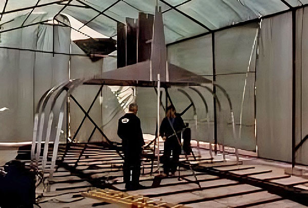
By designing the radius chine hull completely in the computer using specially developed Yacht Design Software, it is possible to have a totally fair round bilge steel or aluminium hull. The hull is designed as a one and one third hull form, the computer then strikes a new center line so the radius of the chine and the curve where stem and bottom join equals the pre- determined chine radius. The purpose of this article is to "walk you through" the process of building a radius chine hull.
Assuming you have selected a suitable design, you will have received your plans and full size patterns and your first job will be to carefully study the plans. An hour of study can save several hours of un-fruitful labour. Keep your full size patterns rolled up in their sealed tube until you are actually ready to start building. Choose a dry day to lay out your patterns on a level plywood or steel floor area which is slightly larger than the total height and width of your hull.
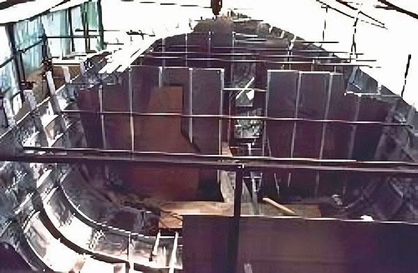
Transfer your patterns on to the steel or plywood using one of the several methods such as Centre punching several points and fairing in the curves with a batten or using a dress-makers’ wheel to transfer the lines on to a temporary plywood floor. The steel area can be future be easily fitted and cut from flat or T bar. The curved constant radius sections, usually between 27" to 36" radius, can either be bent in-house or sent to your local blacksmith or equivalent.
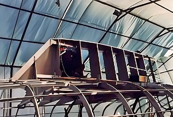
A word on bending flat or T bar on edge. It is possible to get very accurate results by setting up a hydraulic jack in a framework. This simple device will take care of bending all of the deck beams, stem, and other similar items, so it is well worth your efforts to put this device together at this time.
Normally your patterns will show one half of the hull so you simply make two sections over the pattern and open the frame out like a giant clam shell, then check measure for correct width and proceed with the final frame assembly. Many designs call for steel plate web floors, so the bottom of the frame and the web floor can be cut from one piece of plate, with the regular framing extending up to complete the frame.
As the frames are usually intended to be inverted on a strong-back, it is usual to fit a head-stock at a pre-determined location thus providing a constant point for setting up the frames. It is recommended that hulls of up to 65' (20m) be built inverted and extremely beamy or very large hulls are best built upright. Additional bracing by way of 2" x 2" angle is necessary to keep the frames rigid enough to be properly set up on the strong-back. At some point notches will need to be cut in the frames to accept the stringers. You may find the easiest and most accurate way is to set up the frames on the strong-back and mark the stringer positions on all frames, using a fairing batten to ensure a fair set of stringers. Now remove the frames and cut the stringer notches using a cutting torch or disc. Now give the frame a final check against the patterns before re- installing on the strong-back.
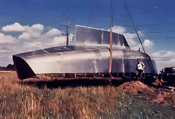
The stem is pre- bent on edge and installed in position. Once the stem and all frames are set up and checked for position and squareness off the centerline, etc, the next job is to install the stringers. Allow the stringers to run a few inches past the expected transom position; they will be trimmed later. Never on any metal hull fully weld the stringers into the slots, simply tack the stringers into position. This will allow you to relieve the stringers and allow them to take a fair shape when installing the plating.
